touch_panel_calibration
功能概述
启动一个 FreeRTOS 任务,初始化触摸驱动芯片,配置触摸芯片基本参数时选择开启校准以及校准方法,校准过程中根据校准状态切换 LCD 显示。 校准完成后,系统会循环侦测屏幕触摸行为,当有正常到触摸时,系统会将获取原始数据转换成校准后的坐标点,并通过串口显示该坐标点信息。
说明:
a).电阻屏才需要执行校准,电容屏不需要。因为电阻屏通过电压变化定位,易受硬件误差和机械形变影响,需校准补偿;电容屏直接检测电容变化,由控制器精确计算坐标,硬件一致性高,无需校准。
b).若选择了电容屏并且开启了校准,不会产生任何效果。
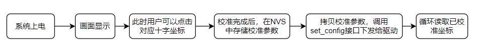
c).示例程序流程:
根据示例中定义的校准点数据量,会在LCD屏幕上依次显示出 “+” 符号。每显示一个 “+” 符号,用户需要触摸其所显示的位置。
程序会读取到触摸点原始数据,不再出现 “ + “ 表示读取完所有校准点。然后进行校准参数计算,并得到原始数据与像素坐标之间进行转换的校准参数(比例、斜率和偏移)。
当前示例默认,会将校准参数存储在 NVS 中。用户也可以客制化定义存储到其他地方。
校准完成后,调用 set_config 接口下发给驱动。
程序循环侦测触摸行为,若用户有触摸,会将触摸的像素点坐标在 log 日志打印出来。
d).示例中的宏定义 “#define LCD_CAL_DISPLAY_OFFSET 20” 的作用如下图
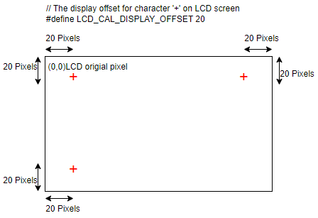
注意: 这只是一个示例仅供参考。用户可以根据自己需求进行修改。
用户可以使用自己的校准算法,但注意需要屏幕配合进行显示 “ + “ 或其他符号。tp_cali_on_lcd.c 中简单的显示十字和清屏函数可供参考。用户也可以用自己的方法如 lvgl 进行显示。
使用其它芯片请修改 prj.config 文件中的宏 CONFIG_BUILD_TYPE_W80x 。
使用其它 GPIO 请修改 build/device_table.toml 中 spim_soft GPIO 定义,或修改 wm_iot_sdk/components/wm_dt/config 中对应芯片的 pim_soft GPIO 定义。建议修改 build 下的,避免影响其它使用 spim_soft 。
环境要求
触摸驱动芯片:
型号:xpt2046 通过 menuconfig -> PERIPHERALS -> Touch driver -> touch Device 中选择 xpt2046 这款触摸驱动控制器。
引脚连接: xpt2046 触摸驱动控制器的硬件配置在 wm_dt_hw.c 文件中进行(默认使用 W802 芯片)
| GPIO序号 | 引脚编号 | 连接描述 | xpt2046 PIN |
|---|---|---|---|
| WM_GPIO_NUM_24 | PB8 | CLK | 16 |
| WM_GPIO_NUM_25 | PB9 | CS | 15 |
| WM_GPIO_NUM_28 | PB12 | MOSI | 14 |
| WM_GPIO_NUM_29 | PB13 | MISO | 12 |
| WM_GPIO_NUM_30 | PB14 | IRQ | 11 |
编译和烧录
示例位置:examples/peripheral/touch_panel/touch_panel_calibration
编译、烧录等操作请参考:快速入门
运行结果
成功运行将输出如下日志
[I] (98) main: ver: 2.3-beta.2 build at Apr 29 2025 10:12:32
[I] (99) main: boot reason 0
[I] (99) main: heap size 271592(265.23KB)
[I] (100) main: flash size 0x800000(8MB)
[I] (760) example: start calibration
[I] (7585) example: Calibration parameters: ax = -0.1263, bx = -0.0004, cx = 494.5495, ay = 0.0001, by = 0.0751, cy = -16.3981
[I] (7589) example: LCD coordinates(x=19,y=252) after calibration.
[I] (7690) example: LCD coordinates(x=19,y=251) after calibration.
[I] (9691) example: LCD coordinates(x=49,y=56) after calibration.
[I] (9792) example: LCD coordinates(x=49,y=57) after calibration.
[I] (9893) example: LCD coordinates(x=48,y=58) after calibration.
[I] (10393) example: LCD coordinates(x=192,y=88) after calibration.
[I] (10495) example: LCD coordinates(x=192,y=87) after calibration.
[I] (10596) example: LCD coordinates(x=192,y=87) after calibration.
[I] (11496) example: LCD coordinates(x=372,y=38) after calibration.
[I] (11598) example: LCD coordinates(x=372,y=37) after calibration.
[I] (12198) example: LCD coordinates(x=393,y=134) after calibration.
[I] (12300) example: LCD coordinates(x=393,y=135) after calibration.
[I] (12401) example: LCD coordinates(x=393,y=135) after calibration.
[I] (13401) example: LCD coordinates(x=214,y=144) after calibration.